
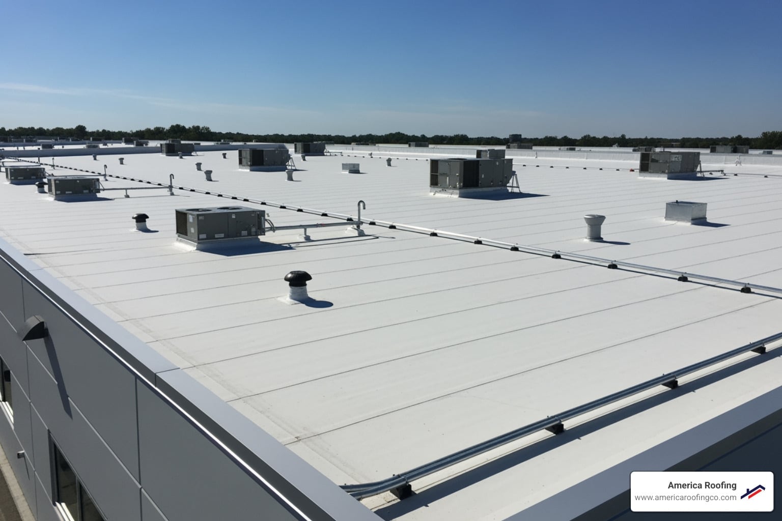
TPO—thermoplastic polyolefin—is a heat-welded single-ply roof membrane commonly used on low-slope buildings. This is an assembly overview, not installation instructions. The selected manufacturer's current details, tested design, local code and project engineering control.
Start below the membrane
Before TPO is installed, the design must account for:
- Structural deck type and condition
- Existing roof layers and moisture
- Vapor and air-control strategy
- Insulation type, thickness and layout
- Cover board or separator requirements
- Wind-uplift design
- Attachment or adhesive compatibility
- Drainage and slope
The GAF mechanically attached system manual uses different application and attachment tables for deck types, insulation, new construction, tear-off and recover conditions. That is why “60-mil TPO” is not a complete specification.
Attachment method changes the design
Mechanically attached
Fasteners and plates secure the membrane or system to the deck. Sheet width, fastening pattern, deck pull-out resistance, perimeter zones and corners affect wind performance.
Fully adhered
Adhesive secures the membrane to an approved substrate. Surface preparation, adhesive coverage, weather and substrate compatibility matter.
Other approved configurations
Self-adhered, induction-welded and ballasted designs may be available for specific products and conditions. Do not swap attachment methods without redesigning the assembly.
Heat-welded seams
Adjacent sheets overlap and are welded with controlled heat, speed and pressure. Jobsite temperature, wind, machine settings and membrane cleanliness affect the weld.
The GAF TPO installation guide describes test welds and seam probing rather than assuming one welder setting works all day.
A quality-control plan should identify:
- Daily and condition-change test welds
- Seam cleaning requirements
- Weld width and overlap
- Probe inspection after cooling
- Marking and repairing voids
- End-lap and T-joint treatment
T-joints and end laps
Where three membrane layers intersect, thickness changes can create a small water path. Manufacturer details may require a cover patch or specific treatment depending on membrane type and thickness.
The GAF architectural details manual separates side laps, end laps, T-joints and field layout details. Those conditions should be visible in the submittal and installation plan.
Edges and perimeter securement
Wind pressure is greater at roof perimeters and corners. Edge metal, membrane termination, blocking, fasteners and flashing need a coordinated design.
Check:
- Continuous wood nailers or approved substrate where required
- Membrane securement at changes in plane
- Tested edge-metal configuration
- Joint covers and corner treatment
- Cleats, fasteners and splice locations
- Tie-in to gutters or scuppers
An attractive fascia does not compensate for weak membrane securement behind it.
Walls, curbs and parapets
Base flashing turns the field membrane up a wall or curb and must be secured and terminated. Counterflashing, coping or another approved termination keeps water from entering behind it.
Pay attention to:
- Maximum unsupported flashing height
- Base attachment
- Inside and outside corners
- High-wall conditions
- Coping joints
- Door thresholds
- Equipment-curb height
Drains, scuppers and overflow
A drain detail needs clamping, target or coated-metal components as required by the system. Scuppers must connect the membrane through the wall without open corners or reverse laps.
The roof plan should show primary and overflow drainage, sump locations, tapered insulation and the finished path of water.
Penetrations and rooftop equipment
Pipes, conduits, supports, vents and irregular clusters need compatible boots, wrapped flashings or sealant pockets. Equipment should have service clearances and a traffic path that does not invite repeated membrane damage.
Do not pitch-pan every irregular condition by default. Use the manufacturer's preferred detail for the shape, temperature and movement involved.
Maintenance after installation
Inspect:
- Welded seams and patches
- Edge and wall terminations
- Drains and scuppers
- Penetrations and supports
- Walk pads
- New equipment work
- Punctures or cuts
- Ponding and debris
Record every trade that accesses the roof. A small puncture discovered early is a repair; one hidden under equipment or standing water can become interior damage.
What to require in a TPO proposal
| Scope item | Required detail |
|---|---|
| Existing roof | Tear-off/recover and moisture findings |
| Deck | Type, condition and repair allowance |
| Insulation | Product, thickness and attachment |
| Membrane | Manufacturer, product and thickness |
| Attachment | Tested design and perimeter enhancement |
| Flashings | Walls, curbs, edges, penetrations and drains |
| Quality control | Test welds, probing and documentation |
| Warranty | Exact issuer, level and eligibility requirements |
Use the broad flat and low-slope roofing guide to compare TPO with other assemblies. America Roofing can evaluate TPO and other systems through its commercial roofing service. To discuss a building-specific scope, request a free roofing estimate.
Primary references